


likes
How to Make Your Own Cat5 Ethernet Cables for IP Cameras
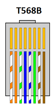
If you are crimping your own ethernet cable for IP security cameras - you’ll need to follow a specific color coding of the twisted pairs. This ensures the is capable of high speed, digital signaling. This standard is called 568B and should be used on both ends of the ethernet cable.
Without 568B the IP cameras (or any network device) will not work. The 568B standard ensures a data connection. If you do not do 568B and use a cable tester, the cable tester may show the cable working. However a cable tester only tests continuity and not data output - so while the ends may be the same it’s not enough for an ethernet data connection.
When installing any ethernet cable be careful not to severely bend or pull the cable - this could break the cable and cause lack of connectivity and/or disconnections.
Step 1: Run the Wire Where You Want it to Go
ProTip: It is helpful to keep it on the spool as you run the wire. It will create less mess and you'll have extra if you have to go around something that wasn't in the plan.
Step 2: Cut the Wire
Cut the cable at the location (both ends - near the NVR and camera). Remember to leave extra to account for future maintenance and for mistakes when crimping your connectors.
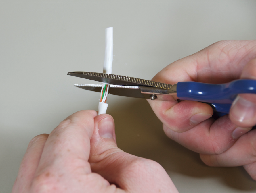
Step 3: Score the Sheath
Be careful not to cut all the way through the sheath and into the twisted pairs.
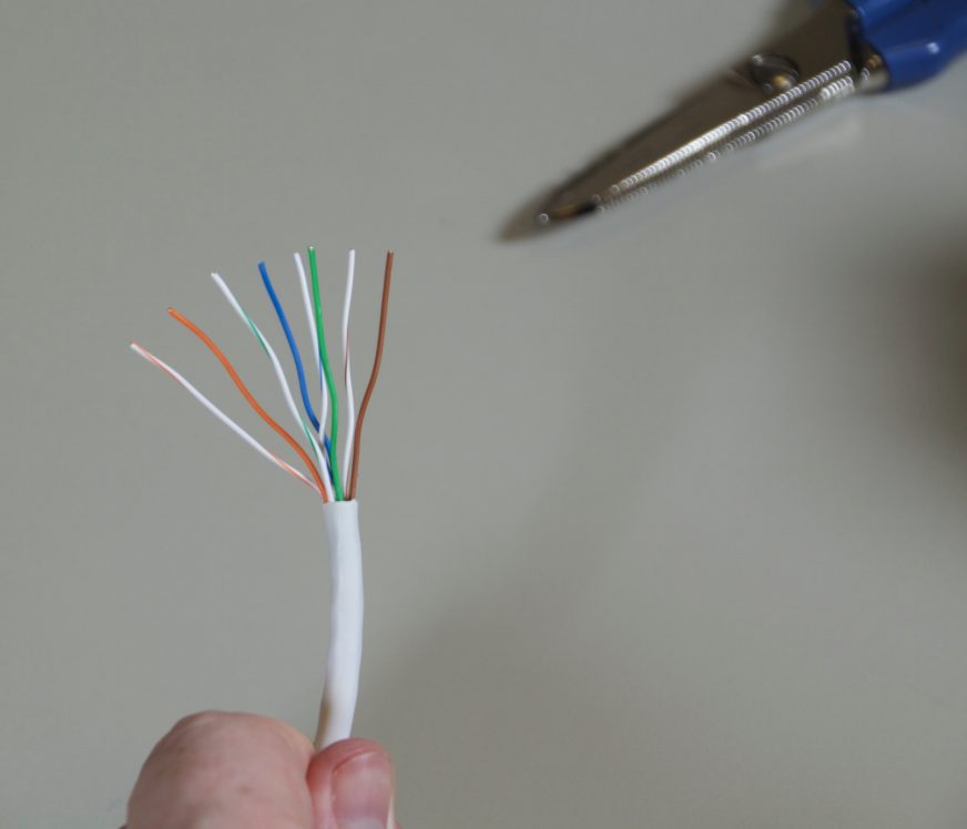
Step 4: Straight and separate pairs
Step 5: Order into 568B Standard
Order them in the 568B standard and cut the length so that the RJ45 pairs are short enough to fit into the RJ45 connector but that the sheath will be near the bottom of the cable. Look at the example below.
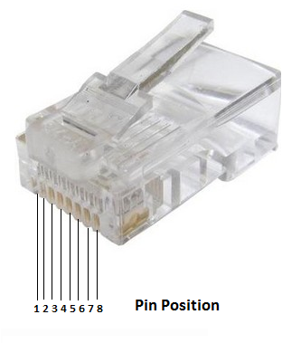
Step 6: Put RJ45 Connector On
Once the copper pairs are in, push towards the end of the connector to ensure the copper pairs are strongly touching the copper end of the RJ45 connector. This is an important step as poorly connected/crimped RJ45 connectors can cause random disconnections or loss of signal.
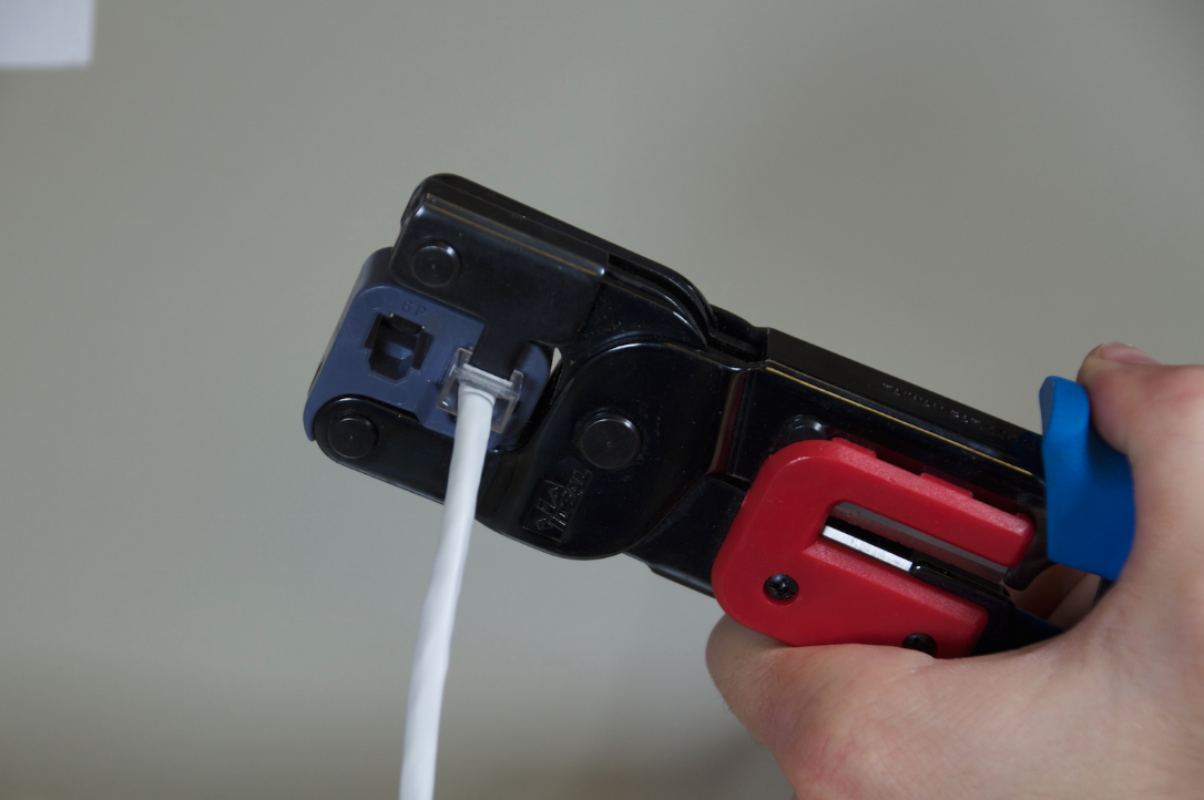
Step 7: Crimp
Get the RJ45 Crimping tool and press down hard until you hear a “click” or “snapping” noise and the crimping tool’s ratchet mechanism releases.
Step 8: Complete
Release the cable and the cable should be usable. Check to ensure the connector is securely fastened to the cable. If you have a cable tester you can test the continuity of the cable (making sure both ends were crimped 568B). Then plug the camera in.
Step 9: Congratulate Yourself
You just saved a bunch of money on installation!
Cable Troubleshooting
If you are having connectivity issues after installation - you may need to recheck the RJ45 connections to make sure this guide was followed correctly. If it continues to have issues and you bench tested the cameras - you may have bent/damaged the cable sometime during installation which may require you to re-run the cable.
Finally, the max distance of standard ethernet is 100 meters, or about 320FT. Any run going above 100 meters may not work or may suffer packet loss which results in dropped signal from the camera and disconnections. If you are running a cable longer than 320FT will the Admiral line series you can enable extended transmission for up to 750FT of cable run by going to Menu-Camera-Selecting the port and enabling extended transmission.
Just Getting Started with Security Cameras?
Get the SCW Beginner Guide!
New to security camera systems? Confused by Analog vs IP? Bullet vs Dome? Indoor vs Outdoor? Don't even know what PTZ means?
No problem! Download the SCW Beginner Guide and get all your questions answered right away!
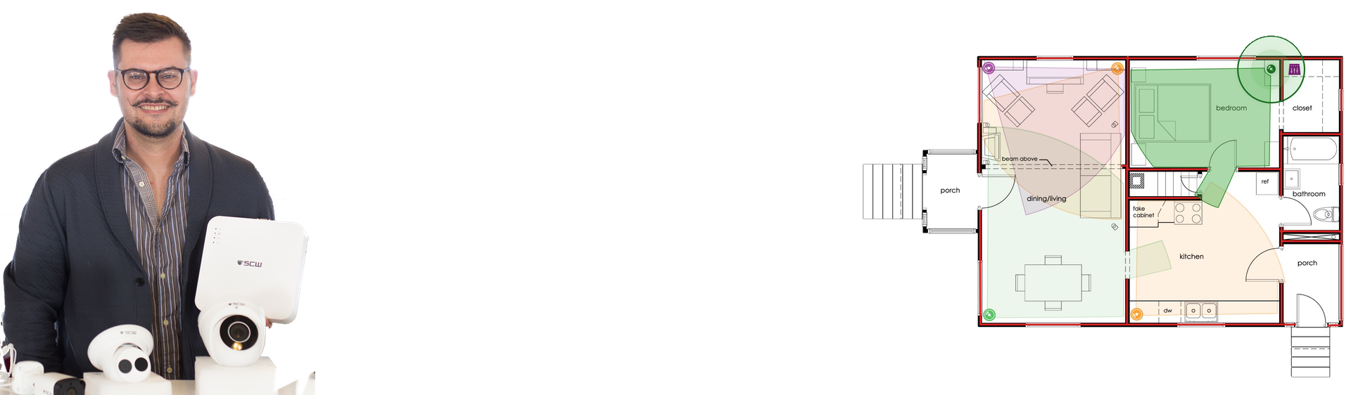
Not sure what you need?
Lean on the experts
We'd be happy to work up a custom quote or take your floorplan and create a security coverage map.
Get aCustom Quote
/ images